Struggling to create clean, reliable solder joints on your LED strip lights? Getting a solid connection without damaging the strips or causing shorts can be tricky.
Luckily, with a few simple steps, you can ensure your soldering is neat, secure, and ready for use.
Keep reading to learn the essential techniques for professional-looking LED strip soldering.
Gather the Right Tools for Soldering LED Strips
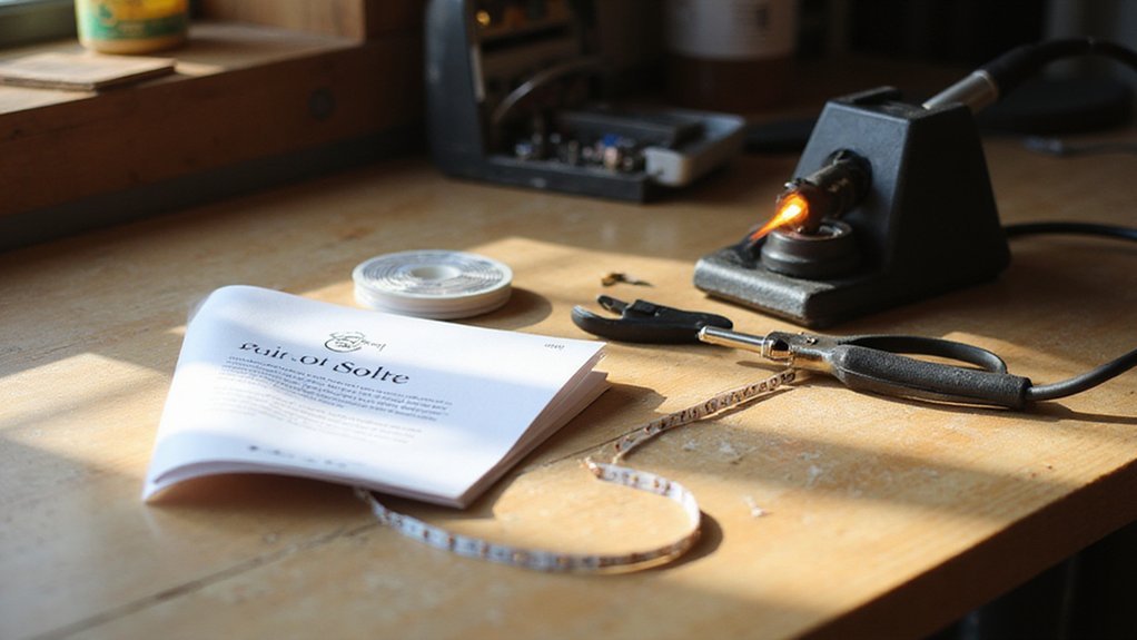
You need specific tools to solder LED strip lights reliably. An adjustable-temperature soldering iron rated between 30W and 60W is essential to control heat and prevent damage to delicate pads. Opt for a chisel tip, approximately 2 to 3 mm wide, as it transfers heat more efficiently than a conical tip. Use 60/40 tin-lead rosin-core solder with a diameter of 0.8 mm for easier flow, or select 63/37 eutectic solder for instant solidification, which reduces the likelihood of cold joints. Lead-free solder, which requires more heat, can be used but demands careful temperature control. Understanding the distinction between floodlights and uplights is also important when considering fixture placement for LED strips.
Choose stranded copper wire—22 AWG for most standard LED strips, and 20 AWG if higher power delivery is needed. Wire strippers are necessary to prepare clean, shiny leads that ensure good electrical contact. Applying flux paste on coated pads improves solder wetting and connection quality. Securing the strip with helping hands or clamps maintains stability during soldering, while copper alligator clips act as heat sinks to protect sensitive components from overheating. Disregard cut marks on the strip and instead trim a sacrificial pixel to expose more copper for a stronger connection. For safety, always use a damp sponge to clean the soldering iron tip, preventing oxidation. Ensure your work surface is stable and non-flammable to avoid accidents during the soldering process.
A damp sponge is used to clean the soldering iron tip, preventing oxidation, while isopropyl alcohol removes flux residues after soldering. Working in a well-ventilated area and wearing safety glasses are crucial safety precautions to protect yourself from fumes and accidental splashes. Additionally, verify that the total current draw of your strip does not exceed the wire gauge rating to prevent overheating and potential fire hazards.
Cut Your LED Strip Only at the Copper Pads
Identify the exact copper pad marking before cutting your LED strip. Use a straight edge and a sharp blade or scissors to cut only along the marked line, which is positioned between the copper pads. Ensure your cut is precise and straight to avoid damaging the circuit. Cutting through the copper pads will break the electrical connection, so always cut between them. The printed cut marks on the strip guide you, typically aligned with the segment spacing, such as every three LEDs, but the copper pads are the definitive cut points. Align your blade carefully to avoid off-center cuts that could compromise the strip’s connectivity. A clean, straight cut preserves the remaining copper for easy soldering or reconnecting later. For a finished installation, consider planning the power source locations to match your under cabinet layout. After cutting, peel back the adhesive to make the strip thinner and easier to close around connectors or corners. Unlike outdoor lighting, LED strip lights do not require a choice between flood or spot beam patterns because they emit a uniform linear light. This same principle of directional airflow applies to ceiling fan direction, which you should change seasonally for optimal comfort.
How to Tin Wires and Pads for Reliable Conductivity
To ensure reliable conductivity when connecting LED strip lights, properly tin both the wires and copper pads before joining them. First, remove oxidation by cleaning the copper surfaces with isopropyl alcohol. This step eliminates dust, residues, and oxidation, ensuring the solder wets the surfaces properly.
Next, focus on applying solder. When preparing the wire, strip just enough insulation to expose a small length of copper—exposing too much can lead to brittleness and weak joints. Apply flux to the stripped wire, then heat it with a clean soldering iron tip and feed solder until a thin, even coating forms on the wire. For the copper pad, heat it first with the iron, then apply a thin, flat layer of solder—avoid overloading, as excess solder can cause shorts. Capillary action will draw solder into the wire effectively when the wire is hot enough, ensuring thorough coverage. Properly tinning both surfaces makes subsequent connections faster and more reliable.
Solder LED Strip-to-Strip or Strip-to-Wire Joints Properly
To properly solder LED strip-to-strip or strip-to-wire joints, ensure that the wires and pads are tinned and aligned precisely. Verify that the copper pads on both strip sections match in number and polarity, especially for RGB or tunable-white types. Keep the strips flat and stable—using tape or helping hands—to maintain perfect alignment of the pads. When connecting wires, match conductor counts and color codes to the correct channels, twisting stranded wire ends tightly to prevent stray strands from bridging pads. Use 18 gauge soft silicone cables for flexibility and ease, as this wire gauge and material simplifies handling and bending. A similar principle applies when replacing recessed can lights, where careful alignment of the new unit’s connectors is essential for a secure fit. Apply your soldering iron to both the pad and the wire simultaneously, allowing the solder to reflow and form a solid, unified joint. Keep the heating brief to avoid damaging the strip. Once the solder flows and bonds, hold everything steady until it hardens. For added durability, plan to reinforce the joint later with hot glue or heat shrink tubing for strain relief, but focus first on making sure the connection is flush, strong, and free of excess solder buildup.
Test, Protect, and Insulate Your Finished Solder Joints
After completing your solder joints, it’s essential to protect them. Slide heat-shrink tubing over each soldered pad and use a heat gun to shrink it until it’s snug around the joint. This provides both electrical insulation and mechanical strain relief, preventing accidental shorts and physical damage. If the heat-shrink tubing doesn’t fit, dab hot-melt glue onto the joint and let it cool to secure the connection. Once protected, re-test your circuit to ensure the connection still functions correctly under operating conditions. Skipping this step can hide issues that might lead to failures later on, so don’t overlook it. If the joint still fails after re-testing, a full power cycle reset may be needed to clear any lingering faults, similar to how a stuck device often requires a hard reboot to restore normal operation.