Thinking about installing recessed lights but feeling unsure where to start? Whether you’re wiring a few fixtures or creating a whole new lighting setup, getting the connections right is key.
By understanding the basic wiring process, you can confidently handle your project from start to finish. Keep reading for a clear step-by-step guide to connect recessed lights safely and effectively.
Start With Safety: Turn off Power and Confirm No Voltage
Start with safety by turning off the power and confirming no voltage before working on the fixture. First, shut off the circuit breaker or remove the fuse for the recessed-light circuit at your main panel. Do not rely solely on the wall switch, as it doesn’t guarantee the fixture is off. After switching off the breaker, use a non-contact voltage tester at the fixture to verify zero voltage. Test your voltage tester on a known live circuit first to ensure it works properly before checking the fixture. Always inspect wiring behind drywall using a voltage tester to confirm power is off, as found looping hot wires can pose a hidden danger. For an additional measure, ensure the ceiling fan direction is set correctly for the season to improve air circulation and comfort. Similarly, when replacing a capacitor in a fan, always check the capacitor specifications to match the old unit’s ratings for a safe and successful installation. To further ensure safety, always follow the manufacturer’s wiring diagram included with the fixture for proper connections.
Mark Recessed Light Locations: Use the Template and Find Joists
To accurately mark recessed light locations, start by sketching the shape of the room on paper and measuring its dimensions. Break irregular spaces into rectangles to simplify your planning, then add these areas together. With your lighting plan in hand, use the manufacturer’s template for placement. Place the template at your chosen location’s center and trace around it with a pencil. Repeat this process for each fixture before you cut into the ceiling. Use a consistent spacing strategy, typically around 3 ft from walls, to ensure uniform illumination across the room. For a more decorative accent, consider installing wall sconce candle holders in addition to your recessed lights to add layered ambiance. You can achieve a clean DIY finish by using appropriate wire connectors for each connection.
Next, verify the joist locations using a stud finder. Slide it across each traced circle to ensure you don’t overlap with a joist. Check in both directions because joists can restrict where you can place a fixture. If the stud finder indicates a joist, shift the template slightly and trace again. It’s also helpful to probe above the ceiling if accessible, to confirm there are no obstructions. Only finalize your marks once you’re certain the space is clear. Before cutting, review the guidelines for track lighting bulbs to ensure compatibility with your fixture type.
Finally, double-check the distances from nearby walls perpendicular to your marked locations. Maintaining consistent spacing ensures your lighting grid stays aligned. Once these steps are complete and the placement is verified, you can proceed to cut into the ceiling material.
Drill and Cut the Ceiling Openings Without Breaking Anything
Start by drilling a small pilot hole at the center of your traced outline. This helps you check for any hidden obstructions like wires or pipes above the ceiling. If you encounter resistance, don’t force the bit, as you might hit framing or piping. Once the area is clear, switch to a drywall saw or a hole saw and cut at medium speed. Keep your drill perpendicular to the ceiling to ensure a clean, round opening. Pay attention to the cavity for any wires that could snag during cutting. If your ceiling has a delicate texture or acoustic panels, score the surface with a utility knife first to minimize chipping and tear-out. Use light, steady pressure while cutting and stop immediately if you come across anything unexpected. Always wear eye protection and a dust mask to stay safe and maintain control during the process. For a precise cut, align the pilot bit of the hole saw with the center cross mark on your template. Selecting the correct recessed can lights for your room’s insulation type ensures safety and prevents heat buildup.
Run Cable From the Switch Box to the First Light Opening
Run the NM-B cable from the switch box up into the wall cavity, then across the ceiling to the first light opening. Choose 14/2 or 12/2 cable depending on your circuit breaker’s amperage—14/2 for 15-amp circuits and 12/2 for 20-amp circuits. Use proper routing techniques to navigate around obstacles such as joists and ductwork. If a joist blocks your path, drill a hole through the center at least 1.25 inches from the edge to provide enough space for cable protection. Secure the cable every 4.5 feet and within 8 inches of the switch box using staples designed for electrical wiring. Leave 12 to 18 inches of slack at the first opening to simplify future connections. The cable must contain hot, neutral, and ground conductors, with the hot wire usually black or red, neutral white, and ground green or bare. This initial run will serve as the feed cable before connecting additional fixtures. Be sure to maintain the switch leg correctly to ensure proper control of the lighting circuit. Validating wiring runs involves drilling through joists with long augur bits to pull wires through drilled holes and avoid excessive ceiling punctures.
Wire Multiple Lights in a Daisy Chain: One Fixture to the Next
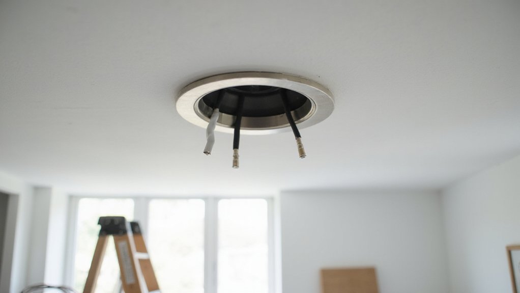
Because you’re connecting multiple recessed lights in a daisy chain, you’ll run a short jumper cable from one fixture’s junction box to the next, instead of pulling a separate home-run cable to each light. This creates a continuous power path that wires each fixture in parallel. Use cable sizing appropriate for your circuit—generally 14/2 for 15-amp circuits or 12/2 for 20-amp circuits. Always refer to wiring diagrams to ensure correct connections: at each junction box, join the incoming hot, outgoing hot, and the fixture’s black lead together, then repeat for neutrals and grounds. The first light receives power from the switch and passes it along to the next fixture. The last fixture only terminates the incoming cable and its own leads. Before connecting, cut the Romex cable to the exact length for each jumper segment to avoid excess wire in the junction boxes. Ensure the junction box volume is adequate for all wire connections and clamps. Additionally, remember to strip the wire insulation carefully to avoid nicking the copper conductor, which could create a weak point in the circuit.
Strip Insulation, Clamp Cables, and Prepare Wires in Each Junction Box
Clamp each cable by its outer jacket—never by individual conductors—to prevent tension from pulling on your splices later. Choose a stripper that matches your wire gauge exactly; this ensures clean, even insulation removal. Strip about an inch of insulation from each conductor, just enough to make a solid connection without exposing more copper than necessary. Score the insulation lightly with your stripper, then gently pull it off to avoid gouging the copper. Immediately trim any nicked or frayed strands, as these are weak points that could cause issues later. Keep the stripped ends clean and straight, with no exposed bare copper beyond where it will connect. Arrange the conductors so they stay accessible and don’t rub against the box edges, which could damage the insulation. Slightly twist wires before pulling to facilitate stripping, as this helps separate the insulation from the copper. Always use a voltage tester to confirm the power is off before handling any wires. Once these steps are complete, you’re ready to make your splices—just don’t do that until all wires are properly prepared. Before wiring, check that the junction box is securely mounted and rated for the fixture weight, as a loose box can compromise the entire installation. Always verify that the box is positioned with clear spacing from obstructions to allow adequate room for wire connections and future maintenance.
Make the Splices: Black to Black, White to White, Ground to Ground
Use black to black, white to white, and ground to ground when making splices. Strip each wire about 1/2 inch, then twist or push the conductors together. For a wire nut, twist clockwise until snug; for a push-in connector, fully insert each stripped end until it locks. Ensure the conductors are fully seated so no copper is exposed after the connection. Use needle-nose pliers to push wires fully into push-in connectors, ensuring they are properly inserted with visibility inside. Similar to a complete build walkthrough for under cabinet lighting, proper insertion prevents loose connections that can cause failure. Unlike wall washer lights, which require a specific beam angle to wash a surface evenly, these general-purpose recessed connections simply need secure splices. When using low profile recessed can lights, ensure the box depth accommodates the splices without crowding the fixture.
Always verify each splice with a gentle pull. If any wire slips out, redo it. The splices must be mechanically stable before you fold them back into the box. Properly matching wire colors and grounding helps ensure safe, reliable connections that meet electrical codes.
Mount the Housing and Snap on the Trim
To secure the housing and attach the trim, start by mounting the housing firmly in the ceiling opening. Pull the four clips inward, then slip the junction box into place, pushing the housing upward until the flange sits flush against the ceiling. Once aligned, push each clip outward until it clicks, clamping the fixture securely. Confirm the stability with a gentle tug; if it doesn’t shift, it’s mounted correctly. Use the appropriate knockout and connector to protect the cable entering the housing, ensuring there’s enough slack in the wire for adjustments and service. Before wiring, always shut off power at the breaker and confirm the circuit is dead with a tester to avoid electrical shock.
For attaching the trim, most models use either coil or rod springs. For coil springs, hook them into the can’s holes, then attach them to the trim before guiding the trim upward into position. For rod springs, squeeze them together and insert the trim into the springs, then push it into place. Before starting, verify that the housing is flush with the ceiling surface to achieve a seamless finish. If you lose the remote or chain, manually turning on the fan requires accessing the pull switch or wall control instead, which is a common issue if the light fixture shares wiring with a fan motor. Recessed lights provide accent or consistent room lighting without occupying surface space. Carefully guide the trim without bending the springs, making sure it sits evenly with no gaps. A secure, flush fit ensures both a professional appearance and durability.
Turn the Power Back On and Test Your Lights
Once you’ve snapped the trim into place and secured all covers, turn the power back on at the breaker. Keep the wall switch off until you’ve confirmed power restoration at the panel. Then flip the switch on to see if the circuit responds correctly.
Next, test each fixture in your run. You want even illumination and immediate startup, so watch for flickering or delay. If you installed a dimmer, rotate it fully through its range to ensure compatibility. This confirms your lighting setup works as planned.
If a light doesn’t turn on, use a voltage tester to check for power at the fixture. If the fixture is energized but still dead, inspect the bulb and socket; loose connections or bent tabs are common issues. If the fixture isn’t powered, recheck your wiring connections.
Always stand back when restoring power for safety, and never rely solely on the wall switch. Turn off the breaker before opening any electrical box to prevent shock or damage. Ensure you confirm the circuit responds correctly before adjusting the dimmer to optimize the room’s ambiance. When selecting ceiling fixtures, note that the number of blades on a ceiling fan can impact both airflow efficiency and motor lifespan.