Wondering how to create a secure, waterproof connection with your wires? Solder seal wire connectors offer a quick and reliable solution.
By the end of this, you’ll know how to prep your wires and apply heat to seal the connection perfectly.
Keep reading for simple steps to master this handy technique.
What Are Solder Seal Wire Connectors?
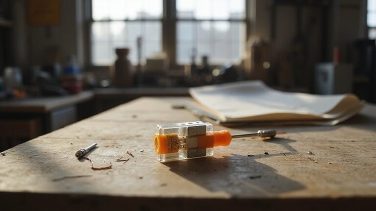
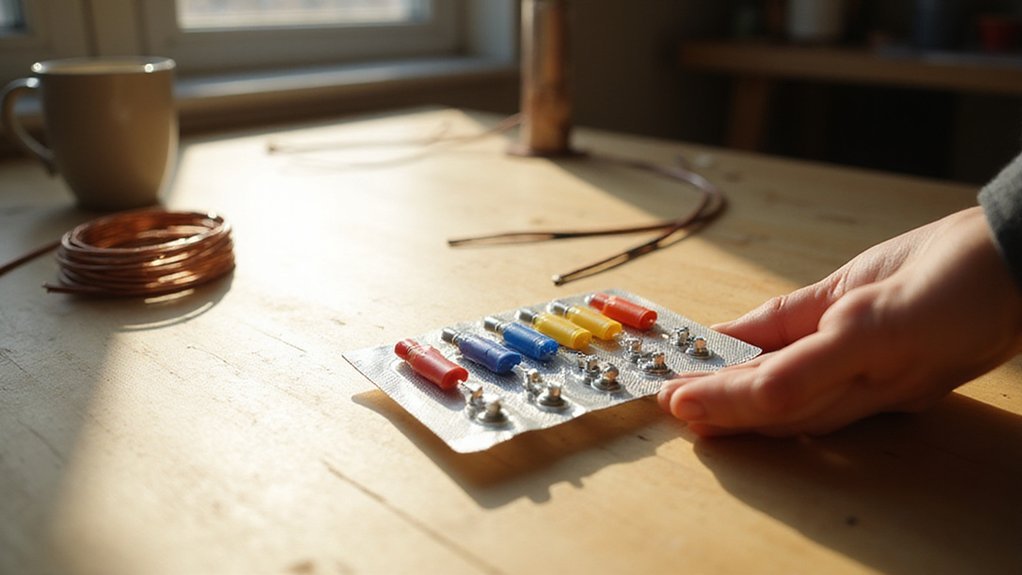
Solder seal wire connectors create a sealed electrical splice in one step by combining solder, heat-shrink tubing, and hot-melt adhesive into a single compact sleeve. They feature a clear polyolefin tube with a low-melting-point solder ring at the center, surrounded by adhesive rings that activate with heat. When heated, the solder melts to secure the connection, while the adhesive rings bond and seal the joint, making it waterproof and corrosion-resistant. This design guarantees a strong, low-resistance electrical connection that’s ideal for environments exposed to moisture. These connectors are especially useful in automotive, marine, and LED lighting applications where reliability and protection from elements are critical. For example, the correct ceiling fan direction for winter requires a clockwise rotation to redistribute warm air, demonstrating how proper setup in any application improves efficiency. When wiring LED strip lights, you can use these connectors to create a clean DIY finish without needing additional tools like a soldering iron.
And because they eliminate the need for separate soldering or tape, they save time and reduce the risk of poor connections. Their flexible, compact shape makes them suitable for tight or awkward spaces, and they perform well in vibrational settings. You can also use them for outdoor sensors, trailer wiring, or any project where quick, waterproof connections are necessary. To ensure a reliable bond, always twist wires together before inserting them into the connector. Overall, solder seal wire connectors provide a fast, durable, and professional-looking splice without complicated steps or additional tools.
How to Prep Wires for Solder Seal Connectors
To prep wires for solder seal connectors, strip 1/4 to 1/2 inch of insulation. Match this length to your connector’s size—smaller connectors need less exposed copper. Over-stripping can cause shorts, while under-stripping weakens the solder bond. Aim for just enough bare wire so it reaches the solder ring without excess, ensuring a snug fit. Always verify that your chosen cutting point avoids any visible cut marks, which are the designated copper sections on LED strips. For low profile recessed can lights, ensure the stripped wires are not too long to fit inside the tight junction box.
Lightly twist stranded wires to prevent fraying, and examine the wire for corrosion or damage—cut out compromised sections. Clean copper surfaces thoroughly; dirt or oxidation can hinder solder flow. Dry-fit the connector onto the stripped wires, making sure the wire overlaps 3 to 5 millimeters inside the ring and that no insulation intrudes. Finally, turn off power to the circuit and stagger splices within the harness to avoid bulk. Proper preparation ensures a reliable, waterproof connection when you apply heat to the solder seal, similar to how a hard reset often resolves glitches in smart plugs.
Step-by-Step Heating and Shrinking Process
Heat the solder seal connector at its center where the solder ring sits using a heat gun set between 750°F and 1110°F for consistent and effective results. Keep the heat gun moving steadily to ensure even heating and to prevent hot spots. Initially, the tubing will shrink in the middle, indicated by the tightening of the colored outer sections. Continue to focus the heat on the solder ring until it turns shiny and flows into the wire strands, usually taking 15 to 30 seconds. Once the solder has melted, gradually direct the heat toward each end of the tubing to complete the shrinking process. The adhesive inside will activate, creating a waterproof seal at the insulation. Do not stop short or prematurely; ensure the tubing conforms fully around the wire with no gaps, typically achieved with a single pass from the center outward to both ends. This technique is especially suited for joining two wires without a soldering iron. The even heating method mirrors how uplights distribute illumination without creating harsh shadow spots. For a clean DIY finish, always match wire colors when connecting to a ceiling fan and light to prevent electrical hazards. For installations near ceilings, consider whether the housing type supports insulation contact to avoid fire risks.
Tools You Actually Need for a Clean Splice
To ensure a clean splice, use heat-resistant pliers or a third-hand tool to hold the connector. Holding a hot splice with your bare hands risks burns and misalignment. While a butane torch is an option, it offers less control and may overheat the connector. Avoid using a lighter altogether, as it’s harder to control and could damage the splice. After heating, verify the joint with a multimeter once it cools. Always trim frayed ends cleanly before splicing to ensure solid contact. This simple toolkit—heat-resistant pliers, a butane torch if preferred, a multimeter, and scissors—keeps your splice safe, stable, and reliable. Unlike many lighting fixtures, these connectors rely on a controlled heat source to melt the inner solder ring. These connectors use a dual-walled construction with an outer polyolefin tubing and inner adhesive and solder ring for secure joints. Overheating the connector can mimic conditions that shorten the lifespan of similar sealed components. For a clean installation, recessed can lights benefit from the same careful heat management to avoid damaging their internal components.
Common Mistakes That Wreck Your Solder Seal Splice
Poor preparation of your wires is one of the most common mistakes that wrecks a solder seal splice. If you strip too little insulation or nick the strands, you compromise the electrical connection. Make sure you remove just enough insulation so the wire strands are exposed evenly, without damage. Before twisting the wires together, create solid anchor points by twisting the ends tightly. Failing to do this means the solder will rely solely on the molten metal to hold the connection, which is less reliable. When placing the splice inside the heat shrink sleeve, ensure the connection is centered so the solder ring melts evenly around the joint. Uneven alignment can lead to weak spots or incomplete sealing. Finally, heat the splice evenly using a heat gun—avoid uneven heating, which can cause solder failure or damage insulation. Never use a lighter as it produces uneven and uncontrollable heat, risking poor bonds or melted parts. Also note that using a smart plug can help you monitor and cut power to devices when not in use, but it won’t improve the quality of your physical splice since voltage fluctuations from poor connections are a separate safety concern. Always check that recessed light housings are properly removed and the junction box is accessible before starting your splice work.
How to Check Your Solder Seal Connector Is Waterproof
To verify your solder seal connector is waterproof, start with a visual inspection. The clear heat-shrink should be fully shrunk without gaps or bubbles, and the adhesive rings must flow outward to form a gasket at the wire insulation. Ensure no exposed copper remains. Proper heating shrinks insulation and melts solder simultaneously, which is the core mechanism for sealing and bonding. This process mimics the safe wiring tips found in soldering LED strip guides for achieving a clean finish. Next, check the solder flow; it should wick into the wire strands, creating a shiny, uniform joint. After cooling, gently tug the connection—if it pulls apart easily, the seal may be compromised. For environmental durability, look for fogging or condensation inside the seal, which indicates moisture intrusion. To test the seal integrity more thoroughly, perform a continuity test—while it confirms electrical connectivity, it doesn’t guarantee waterproofing. For a stricter assessment, an insulation-resistance test below 10 megaohms suggests moisture presence within the connection.