If you’re wondering how to safely join three electrical wires in a single connection, you’ll need the right tools and techniques. A 3-way wire connector makes this easy by gripping all conductors securely without twisting or soldering.
Ensuring the connection is stable and safe is crucial. Keep reading to learn how to choose the right connector and install it properly.
What Is a 3-Way Wire Connector and How Does It Work?
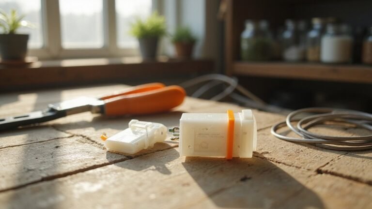
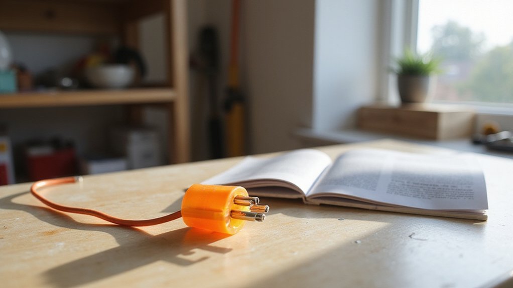
A 3-way wire connector is designed to connect three electrical conductors securely in one junction. To use it, start by stripping the insulation from each wire to the length specified by the connector’s design. Insert each conductor fully into the connector’s clamping mechanism or contact point, ensuring a firm fit. This mechanical connection maintains solid electrical contact across all three wires, preventing looseness or accidental disconnection over time. Unlike traditional methods that require twisting wires together or soldering, a 3-way connector does the work automatically with its built-in clamp. This makes the process faster, cleaner, and safer, providing a stable, reliable link necessary for branching circuits or combining multiple wires in a single location. Once inserted and clamped, the wires are securely held, allowing current to flow uninterrupted through the junction. Each connector is rated for temperatures up to 257°F and a maximum voltage of 24 volts, making it suitable for various low voltage electrical projects. This design is ideal for landscape lighting systems where multiple fixtures must be connected to a single low-voltage cable run. For optimal safety, always verify the wire gauge compatibility with the connector’s specifications before installation.
3-Way Connector Types: Terminal Blocks, Butt Connectors, and In-Line Splices
Terminal blocks, butt connectors, and in-line splices each serve distinct roles in wiring connections. Terminal blocks are modular, insulated units with screw or spring clamps that provide a semi-permanent connection. They come in single-level, dual-level, and three-level versions, accommodating various wiring densities. Barrier-style terminal blocks separate individual connections with a plastic barrier, making them suitable for organized, maintenance-friendly setups. Feed-through terminal blocks enable compact, multi-wire-to-wire connections, ideal when space is limited. When selecting a terminal block, you should choose a terminal rated at least 150% of the maximum expected current to prevent overheating. For LED strip projects, you must also cut the strip only at designated marks to avoid damaging the circuit.
Butt connectors and in-line splices focus on end-to-end conductors. Butt connectors are crimped onto wires with a cold-crimp procedure, creating a permanent, high-strength connection perfect for environments with vibration. In-line splices, on the other hand, join wires directly in an inline configuration, often through mechanical set-screw or crimp methods, allowing for quick field repairs. Always ensure your connector type matches the wire gauge and cable insulation, as choosing incompatible components can lead to unreliable connections or damage over time. For outdoor installations, a weatherproof sealant should be applied over connections to prevent moisture ingress.
When to Use a 3-Way Connector in Automotive, Lighting, and Control Systems
A 3-way connector is ideal when you need to join three conductors into a single, organized junction. In automotive wiring, a sealed 3-way connector is essential for lighting systems or sensor circuits that are exposed to vibration and moisture. Using the correct seal ensures reliable connections in harsh conditions. Proper ceiling fan placement ensures that airflow reaches all corners of the room without obstruction. For engine control applications, selecting a connector with the appropriate pinout for power and data lines helps maintain proper functionality without risking damage or miswiring.
In lighting installations, a 3-way connector simplifies creating T-branches or Y-branches from one power feed to multiple fixtures. Opt for weatherproof versions for outdoor LED or landscape lighting to resist the elements. In control systems, a 3-way connector efficiently carries power, ground, and control signals from sensors or switches. Matching the connector to your environment and voltage requirements ensures longevity and safety. Employing proper crimping techniques with ratcheting tools ensures secure mechanical and electrical connections in these systems.
How to Match Wire Gauge, Stranding, and Connector Ratings
To match wire gauge, stranding, and connector ratings, you need to convert each wire’s AWG value to its circular mil area (CMA) because AWG numbers are inversely related to wire thickness. Thicker wires have lower AWG numbers and higher current capacity. For multiple wires in a splice, sum the CMA values, not the AWG numbers. For example, two 16 AWG wires each have a CMA of 2,580, and one 18 AWG wire has 1,624 CMA. Adding these gives a total of 6,784 CMA. Select a terminal or barrel rated for this combined CMA, rather than just the largest wire involved. For instance, since pure copper cabling is recommended to avoid performance loss, always verify the wire material before summing CMA values for the connector rating. If you suspect any connectivity issues, treating these connections with the same care as a device reset can prevent intermittent failures. Check the manufacturer’s range chart to ensure the connector can handle the combined CMA and mix of gauges. Using a connector rated for a range, such as 14–18 AWG, can simplify the process. When replacing recessed can lights, always confirm the existing junction box rating to ensure the new connector can handle the total CMA of the circuit wires. Match stranding type—solid or stranded—to the terminal’s crimp profile to ensure a reliable connection. Lastly, verify that the circuit amperage matches your wire choice: 14 AWG for 15-amp circuits, 12 AWG for 20-amp circuits, before making any terminations. Just as with cutting LED strips, confirm the connector’s maximum voltage rating matches your circuit to prevent arcing or overheating at the splice point.
How to Crimp a 3-Way Connector Correctly (Step-by-Step)
Position the connector carefully in the appropriate die of your crimp tool. Make sure it is placed squarely in the center and that the tool is held perpendicular to ensure even deformation. For open-barrel connectors, ensure that both the conductor section and the strain-relief section are properly aligned before crimping. Squeeze the tool firmly in one steady motion until the ratchet releases, indicating that the crimp is complete. Before beginning, ensure your connector gauge matches the wire size, just as you would check the wire gauge when replacing a ceiling fan to avoid overload. Always verify the circuit is off before handling any wiring to prevent electrical shock. Just as seasonal fan direction optimizes airflow efficiency, matching connector gauge to wire size prevents poor electrical connections.
After crimping, inspect the connection thoroughly. Perform a gentle pull test on the wire to confirm the conductor is securely attached and does not slip out. Check that the wire insulation is fully covered by the crimp and that no conductive strands are exposed outside the barrel. The crimp should be uniform and square, without crushing or damage to the connector or wire. Always cross-check connector stamps for gauge compatibility before crimping to avoid size mismatches.
5 Common 3-Way Connector Mistakes and How to Avoid Them
Even with a perfect crimp, a 3-way circuit can still fail if wiring mistakes happen. The most common error is misidentifying the common wire, which should connect to the dark terminal, not the traveler terminals. Using color coding can help, but always verify with wiring diagrams to avoid confusion. Second, swapping the traveler wires causes incorrect switching operation. To prevent this, use a multimeter to confirm the pair of traveler wires rather than relying on visual cues alone. Third, loose connections create fire hazards and reduce reliability. Ensure terminal screws are tightened fully, then gently tug on each wire to confirm a secure connection. Fourth, improper stripping can leave too much bare wire or too little making contact. Match the strip length to the connector’s gauge guidelines to maintain proper connection. Perform tug tests to confirm secure attachment, as a loose connection is a common safety risk. The color of the common wire is typically black or dark, not white or green, which helps in identifying the common wire during installation. Always check the power is off before handling any electrical connections, just as you would verify the bulb is cool before removal. Finally, never restore power before double-checking your work. Always test for continuity first to catch mistakes before energizing the circuit. Selecting the correct connector type for the wire gauge ensures a tight and safe crimp.
Why You Need a Waterproof 3-Way Connector for Outdoor and Wet Locations
A waterproof 3‑way connector is essential outdoors because it prevents moisture from entering the connection. Outdoor wiring faces rain, humidity, and pooling water, all of which can cause corrosion. Standard connectors cannot block moisture effectively, leading to corrosion that weakens conductivity and shortens your system’s lifespan. Choose a true waterproof connector rated IP67 or IP68. IP67 handles temporary immersion up to 1 meter for 30 minutes, while IP68 is designed for continuous or deeper submersion. Applying silicone, grease, or petroleum jelly inside the connector adds an extra layer of protection against moisture ingress. Color coding the wires allows you to quickly identify functions, reducing installation errors. Integrating surge protection safeguards your landscape lighting or irrigation system from voltage spikes. Without these features, your outdoor LED, security, or solar circuits are vulnerable to failure. For direct burial or wet locations, weatherproof connectors alone are insufficient; you need truly waterproof connectors to ensure durability. Before installation, practice a safe disconnection method using the proper tool to release the internal locking tabs, which prevents damage to the contacts and wires. This type of connector also supports a maximum current of 24A and a voltage of 450V, ensuring it can handle demanding outdoor loads safely. As when replacing bulbs in under cabinet fixtures, turning off power at the circuit breaker is a critical first step to prevent electrical shock. For those familiar with changing recessed fixtures, remember that pulling the trim straight down is the proper technique to access the bulb without damaging the housing.
How to Install a 3-Way Connector Safely in a Junction Box
To install a 3-way connector safely in a junction box, begin by turning off the correct circuit breaker and verifying the circuit is de‑energized with a non‑contact voltage tester. Never rely solely on the breaker’s position, as it can sometimes be mislabeled or malfunction. Next, securely mount your junction box to a stud or joist to prevent movement or stress on the connectors. Bring each cable into the box through an approved clamp, leaving about 6 inches of conductor inside for easy access. Ensure the cable sheath extends approximately 1/4 to 1/2 inch past the clamp to protect the conductors and meet code requirements. Then, strip approximately 3/4 inch of insulation from each conductor end, taking care not to nick or damage the wire. When using metal junction boxes, prepare knockout openings with a flat-head screwdriver and secure cables with metal conduit connectors and nuts using proper tightening methods for safe wire entry. Understanding the fixture’s mounting and support requirements helps ensure it is safely secured. Follow local electrical codes precisely for wire color identification. Always connect the ground wires first—bare copper or green—to a listed connector, establishing a solid safety bond. Add a pigtail if needed to bond the metal box to its ground screw properly. Next, match the black (hot) wires to each other and white (neutral) wires to each other, using the appropriate wire nuts for secure connections. After fastening each nut, tug gently on the wires to verify the connection is firm and won’t come loose. Always double-check that all connections are properly insulated before folding any wires back. While these wiring steps guarantee safety, note that devices like smart plugs can also reduce energy waste by automatically cutting power to unused electronics. Finally, neatly fold all conductors into the box, install a solid cover plate, and restore power only after confirming all work is complete and safe. Keep the junction box accessible for future inspections or modifications.